This was originally written in 2008 as a forum post for the now defunct G Scale Mad forum.
Appologies for the basic formatting of this page, I've simply inserted enough html tags using Notepad to get it to work!
Nick Falconer 04 Jan 2012
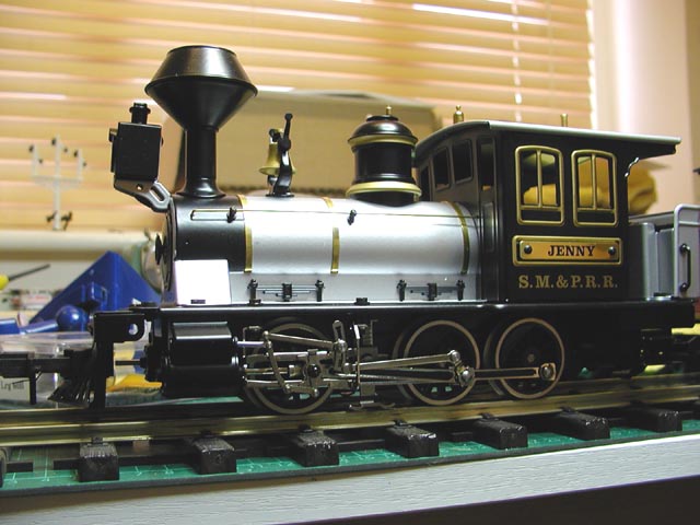
Something a little different to the usual LGB, Aristo & Bachmann etc. locos we normally see on the forum: This is a Maerklin MAXI loco that I particularly wanted as it’s named in honour of my long-suffering wife who has put up with me filling our house with trains of all sizes over the last 20 years! It’s of quality metal construction, basic details and toy-like with exposed screws etc. but beautifully made and runs superbly.
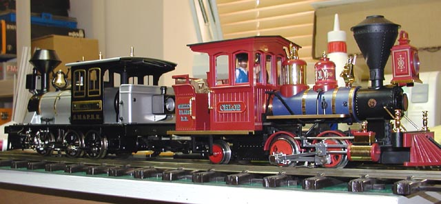
It doesn’t look too bad against small LGB locos like “Chloe” and “Olomana” except for the obvious scale difference in the cab area. I think the average LGB engineer will have a bit of trouble getting on board! I would expect other MAXI locos to be of similar general construction with regard to fitting a DCC decoder.
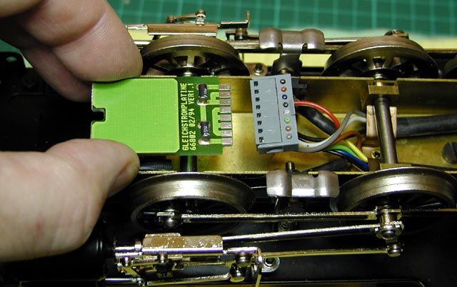
Access to the chassis cavity and wiring is via removal of a cover plate, secured with a single screw at one end and a lug at the other.

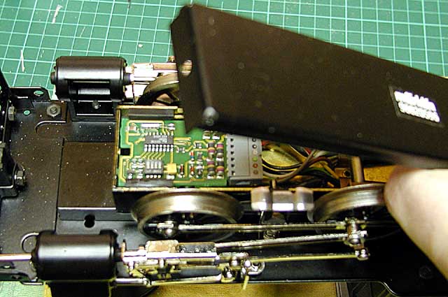
The loco comes fitted with a Maerklin Delta decoder (not DCC compatible). The decoder is supported in a plastic mount and slides backward to remove.
... and is also provided with a DC blanking plate for analogue use.
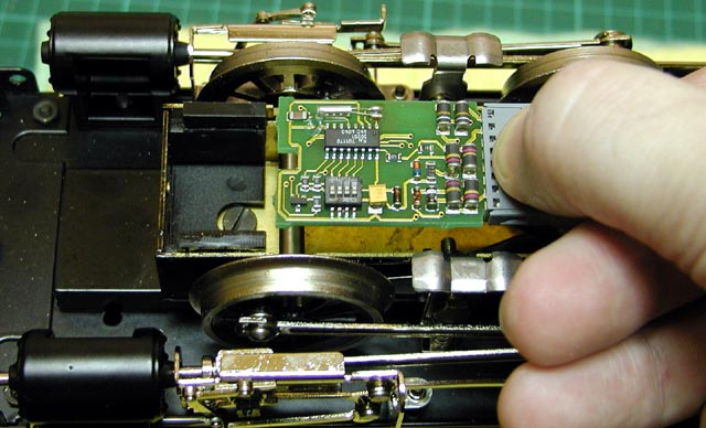
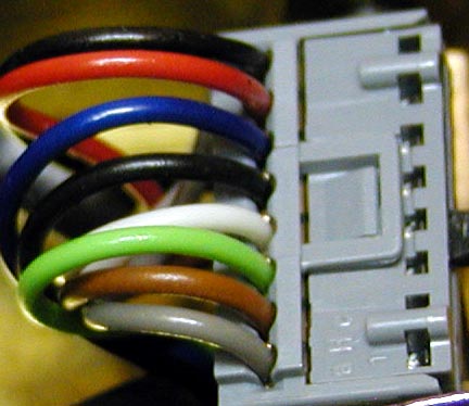
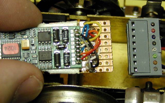
The decoder socket has 8 connections. The decoder connections and the socket are double-sided but I noticed that the DC blanking plate is only single-sided. With my trusty multimeter and mark 1 eyeballs I identified the wire colours as: (from top to bottom of the photo below)
| 1) | black | = rear light (negative) |
| 2) | red | = left rail |
| 3) | blue | = motor connection #1 |
| 4) | black | = lights common (positive) (rear light) |
| 5) | white | = lights common (positive) (front light) |
| 6) | green | = motor connection #2 |
| 7) | brown | = right rail |
| 8) | grey | = front light (negative) |
Note: the smoke unit is wired direct to track power via a switch in the cab. Fine by me, I left it as-is! (You can see two wires to each track connection, one brown and one yellow don’t go via the 8 pin socket – these are the smoke unit wiring).
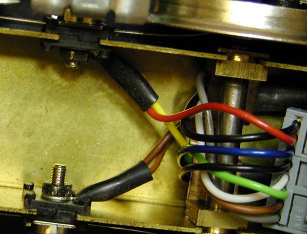
(btw, I don't know for sure what voltage the smoke unit is intended for, but at the 18v DCC track power it gets from my NCE system it smokes extremely well! I hope it lasts!)
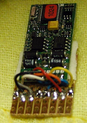
Now, the really useful thing is that the pin pitch of the socket matches the commonly used copper strip-board used for simple home-brew electronic circuits, so all that’s needed is to cut and file a suitable piece with 8 strips so that it fits nicely in the socket. Then wire up your chosen decoder to the strip-board to match the function of each pin. I chose to make the piece of strip-board long enough to partially mount the decoder using a sticky pad. All copper tracks were cut through behind the soldered connections to isolate the rear half of the strip-board where the decoder is mounted. (OK, later I realised I might as well have mounted the decoder on the other side of the strip board in the first place!)
The loco appears to draw only 200mA – 300mA running light on rollers, plus maybe another 200mA when the smoke unit is switched on (but the smoke unit current draw is irrelevant, as it’s not wired through the decoder). In the past, for a small G loco like this I’ve used a high power HO decoder such as a Zimo MX69H or CT Electronik DCX51–2 (which handle 1.5A to 1.8A peak and give some headroom if the loco stalls). However I had a Lenz 1024 (1A peak) sitting around, so this has been fitted and I’ll see how it goes. I’m only expecting the loco to perform light duties! A little experimentation with orientation of the track and motor connections was needed to ensure that direction and lighting worked correctly under both DC and DCC. I finally ended up with:
| 1) | decoder yellow | -> socket black | = rear headlight (negative) |
| 2) | decoder red | -> socket red | = left rail |
| 3) | decoder orange | -> socket blue | = motor connection #1 |
| 4) | decoder blue | -> socket black | = lights common (positive) (rear light) |
| 5) | (link to pin #4) | -> socket white | = lights common (positive) (front light) |
| 6) | decoder grey | -> socket green | = motor connection #2 |
| 7) | decoder black | -> socket brown | = right rail |
| 8) | decoder white | -> socket grey | = front light (negative) |
Strips #4 and #5 were simply linked together using a blob of solder.
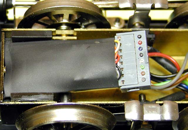
The mounted decoder was then plugged back into the socket. You need to be sure the decoder is isolated from the metalwork of the chassis. Insulation tape will probably do fine, but I was fortunate to have available a dedicated decoder sleeve supplied with a recent Hornby OO loco, which fitted perfectly. (Might have to go in search of more of these sleeves as they’re very useful!) Site the decoder nicely in the chassis where the old Delta decoder lived, replace the cover plate and Job Done!
Nick